MTR_Crest Parameters

Contents
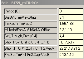
8 switches control actual output to the chart:
Parameter 2, Field 2 . . . Stats
Parameter 4, Field 3 . . . Trough/Crest Fib Fence w/dBias Filtering
Parameter 6, Field 1 . . . Momentum Cap/Cup, Trough Fib Fence no dBias filtering
Parameter 6, Field 3 . . . Trend Vectoring Thermometer to Thermometer
Parameter 7, Field 1 . . . Fib Fence Fold-Over Level_Trough
Parameter 7, Field 5 . . . Fib Vectoring and Momentum Wave
Parameter 8, Field 1 . . . Time Fence Selection
Parameter 8, Field 4 . . . Thermometer Cap Styling and Opposing Force Channeling
These switches can be used individually and/or combined to make the chart suit your individual trade style.
Multiple dlls can be placed on a chart with different settings to create the trade structure and clarity desired.
(i.e. line style, color, symbol, sizing, etc.)
If all 8 of the above switches are set to zero (0), there is no output to the chart.
All other switches set the math and decision logic that is used internally in the dll to create the structure desired. Details of all options for all switches are found below.
Field 1: Fibonacci Trader's 'Own period
(Burton Cycle Tools use only the 'Own' period)
|
Options:
Field 1: Square of 9 Vibration_Momentum Wave
(Sqr9Vib is added to the root of the square of the range of the chart bar then re-squared)
Options: -6 to 6
Example: 9 tick range bar chart. [9^ = 81, 9 + 3 = 12, 12^ = 144] So on a 9 tick range bar chart a 3 yields a Sqr12 momentum wave on a Sqr9 chart. A 13 tick range bar chart would have a Sqr16 momentum wave on a Sqr13 chart.
Notes: This process yields the vibrational momentum wave of the chart as a function of incremental 180* units +/- the square of the range of the chart. [It should also be noted that consistent throughout Burton Cycle Tools the concept of 3 and 270* carry the same meaning. In general . . . the decision is whether to use a 3 or a 4 setting.
Field 2: Stats
Options: 0 = No Stats 1 = Show Stats
|
Options:
Field 1: Time Factor Trough
What 'differential' Time factor do you want to use in the rising leg of the wave for construction of the Trough Fib structure? Default = 1.66
Field 2: Time Factor Crest
What 'differential' Time factor do you want to use in the falling leg of the wave for construction of the Crest Fib structure? Default = 1.66
|
Options:
Field 1: Momentum Look Ahead Factor
What 'differential' Momentum factor do you want to use for construction of the Wave Fib structures? Default = 2.2 (Note: 2.235 is the SqrRt of 5, the hypotenuse leg of the 3-4-5 Pythagorean Theorem Triangle, appears in the fractional expression for the golden ratio, and then naturally figures in the closed form expression for the Fibonacci number sequence, ie don't leave home without it!)
Field 2: Auto Fib Select
What Fib level and time do you want to use for the endpoint of the Fib vectoring when it's turned on? Effectively this establishes the run-rate of the fib vector over time.
Options: 0 = Manual using the current trough settings (Parameter 6, Field 2, Parameter 7, Field 2) 1 = Auto using current Trough External Fib level and Tm21 2 = Auto using current Crest External Fib level and Tm21
Field 3: Auto Directional Bias
Options: 0 = Off 1 = Use Trough Fib Fence for filter (Parameter 6, Field 2, Parameter 7, Field 2) 10 = Display Filter Fence using Line #4 2 = Use Crest Fib Fence for filter (Parameter 6, Field 4, Parameter 7, Field 4) 20 = Display Filter Fence using Line #3
|
Options:
Field 1: Select Trough (Alternatives)
This switch no longer used in this dll. Default = 4
Field 2: Select Crest (Alternatives)
This switch no longer used in this dll. Default = 4
|
Options:
Field 1: Show Trough Support or Resistance
Options: 0 = Off 1,3 = Show momentum LkAhd as Support 'Cup' using Lines #7 & #8 -1,-3 = Show momentum LkAhd as Resistance 'Cap' using Lines #7& #8 abs>(9) = Show trough fib fence and support/resistance selected (Example: 10,-10,30,-30 shows fence and momentum S/R, 60 shows fence only)
Field 2: Trough Fib Level
Options: 0 = Off Else: Can be any number, however, I use Fib levels which have meaning as related to sup/res, or breakout levels, or time, etc.
Field 3: Show Crest Support or Resistance
Options: 0 = Leaves Crest TmLkAhd marker using Line #7 6 = Off 60 = Show Thermometer Trend Vectoring using Lines #6, #8 & #2
Field 4: Crest Fib Level
Options: 0 = Off Else: Can be any number, however, I use Fib levels which have meaning as related to sup/res, or breakout levels, or time, etc.
|
Options:
Field 1: Trough Time Count 1
Options: 0 = Origin of Count (can provide a level of sup/res if desired, essentially the base of a fib zone square) using Line #3 (overrides fib vector but not crest fib fence) 13 = Standard (Example: if set to 13, the fold-over level would display from count 13 to 21, an 8 count lead-in into fold-over threshold, ie a decision time) 22 = 1 beyond Field 2 setting of 21, effectively turning off display of the fold-over level
Field 2: Trough Time Count 2
Options: Standard setting is 21 (primary direction filter)
Field 3: Crest Time Count 1
Best set to 13. When Fib Vectoring is turned on this will show the vector end level (fold-over) from count 13 forward using Line #4. If trough Fib fence is being displayed it will overwrite this level when rotation occurs. Setting a count less than 13 will break up the Fib fence and be confusing.
Field 4: Crest Time Count 2
Must be 21 as this is the primary structure of this dll. Places Thermometer at 21 count.
Field 5: Fib Vectoring and Momentum Wave
Options: 0 = Off 1 = Show Fib Vectoring (uses setting of Parameter 4, Field 2) using Line #3 and displays fib vector end level using Line #4. 2 = Same as 1 + turns off display of fib vector end level. >9 = Shows momentum wave using Line #1 (doesn't work well if Parameter 8, Field 4 <> 0)
|
Options:
Field 1: Fence Select (Output)
Options: 0 = Off (default for this dll) 6 = 21 marker only + all the other features of this dll 7 = no 21 marker + all the other features of this dll
Field 2: Fence 1 (Time Threshold)
(From what Time Count along the Friction Vector from the Trough/Crest do you want to construct Time Fence #1?) Default = 17 (Note: 13 is a standard since it is midpoint and provides clarity to price action, relative to midpoint, from cycle to cycle) (Times: 17, 21, 26, 34 are significant as fences) (Larger Times: 45 is extremely significant, 52, 72, 90 can be interesting)
Field 3: Fence 2 (Time Threshold)
(From what Time Count along the Friction Vector from the Trough/Crest do you want to construct Time Fence #2?) Default = 34 (Note: 13 is a standard since it is midpoint and provides clarity to price action, relative to midpoint, from cycle to cycle) (Times: 17, 21, 26, 34 are significant as fences) (Larger Times: 45 is extremely significant, 52, 72, 90 can be interesting)
Options: 0 = Off 1 = Show External Fib level past 21 count when Trend vectoring is On (Parameter 6, Field 3 >9) 2 = Show Internal Fib level past 21 count when Trend vectoring is On (Parameter 6, Field 3 >9) Default = 2 (not used that much)
Field 4: Show Thermometer Cap and/or Opposing Force Channeling
Options: 0 = Off 1 = Show Thermometer Cap using Line #1 + Thermometer to Thermometer Trend using Line #6 11 = Same as 1 + Lead-In Cap marker using Line #2 10 = Show only Thermometer Cap using Line #1 2 = Same as 1 using Line #2 21 = Same as 2 + Lead-In Cap marker using Line #1 20 = Same as 10 using Line #2 3 = Same as 1 using Line #8 30 = Same as 20 using Line #8 31 = Show Thermometer Cap using Line #9 + Thermometer to Thermometer Trend using Line #6 + Lead-In Cap marker using Line #1 32 = Same as 31 except using Line #2 for Lead-In Cap marker 33 = same as 31 except using Line #8 for Lead-In Cap marker 4 = Show 2nd Fib Vectoring (ie channel) at specific Crest LkAhd Time Factor (Opposing Force) 40,41,42,43,44 = (Line # output variations of #3 & #4) 44 & 5 = (probably the most useable if you want to see the channeling)
|